a) Traditional WDM networks with fixed spacing grid (50GHz); (b)

By A Mystery Man Writer

1 Schematic diagram of the 2-D scalable true-time delay PAA
Transmission loss spectra from port IN to ports THROUGH and DROP

Transmission loss spectra from port IN to ports THROUGH and DROP

Experimental setup: ECL: external cavity laser; PC: polarization

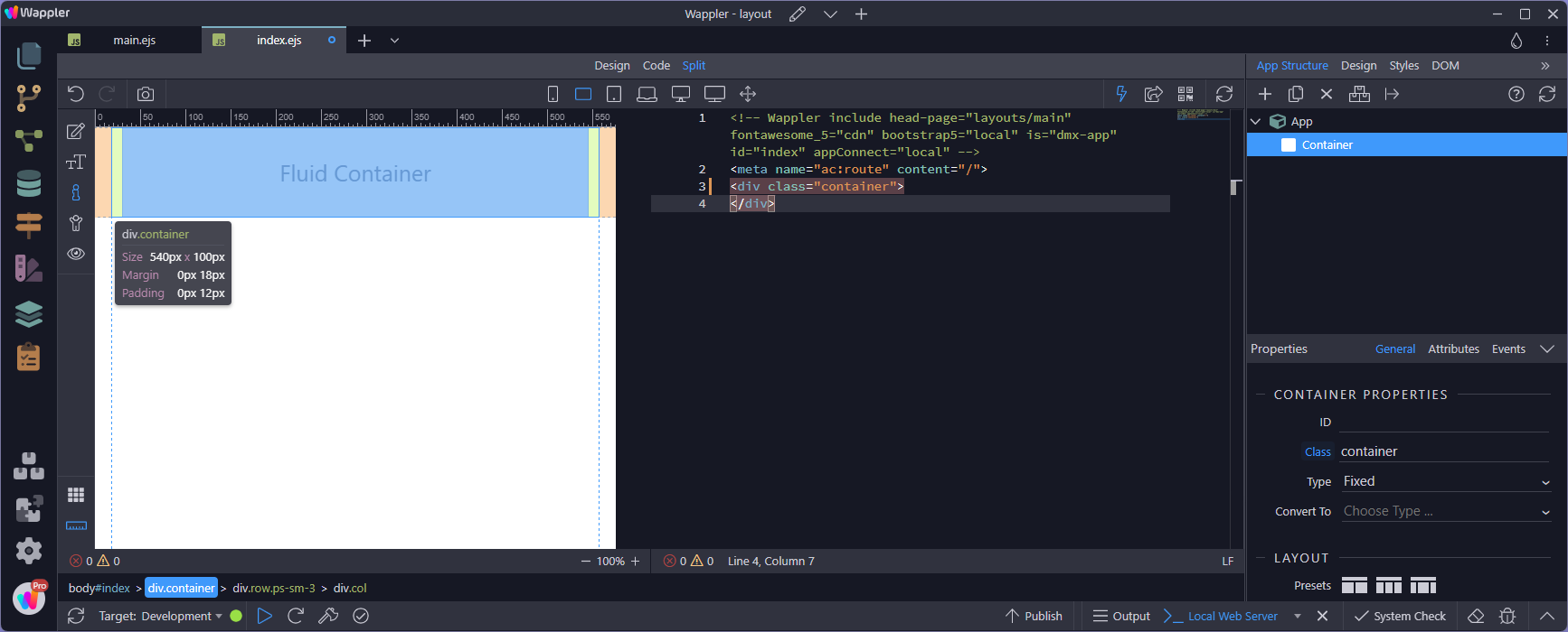
PDF) LCoS-Based Wavelength-Selective Switch for Future Finer-Grid

Figure B.4: Cost ratio (bands, B=4)/(no bands, B=1); x-axis labels

Structure used to model the switch switching fabrics is denoted by

a) Traditional WDM networks with fixed spacing grid (50GHz); (b

PDF) LCoS-Based Wavelength-Selective Switch for Future Finer-Grid

Min ZHANG, Zhejiang Medical University, Hangzhou

Experimental set-up to select a 160 Mbit/s data-channel from 51.2

Figure C.1: A broadcast-and-select architecture as proposed in

Cost variables used for the cost analysis.

PDF) LCoS-Based Wavelength-Selective Switch for Future Finer-Grid

a) Traditional WDM networks with fixed spacing grid (50GHz); (b


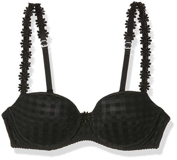
- Marie Jo Avero Balconette - Perfect Fit Lingerie
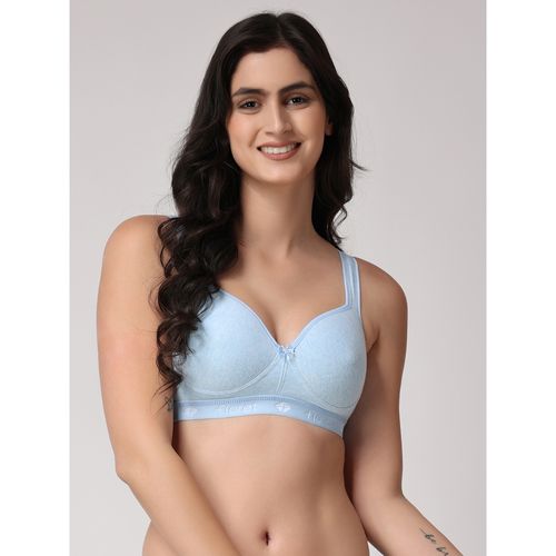
- Buy Floret Heavily Padded Full Coverage Blue Sports Bra Online
- VIRTUE CODE Balance Face Masks - Soft 3 Ply Comfort Face Masks, Black Disposable Face Mask 50 Pack. Black Colored Masks. Adults Mens and Womens Disposable Face Masks : Industrial & Scientific

- Shapewear For Women Plus Size Backless Built In Bra Body Shaper Seamless With Open Body Suit Lace Lingerie, Black, Medium : : Clothing, Shoes & Accessories

- Sexy Women Corsets Body shaper Plus Size Lace Up Overbust Bustier Waist Cincher
